LIKE YOU, QUALITY IS OUR TOP PRIORITY.
CONTACT US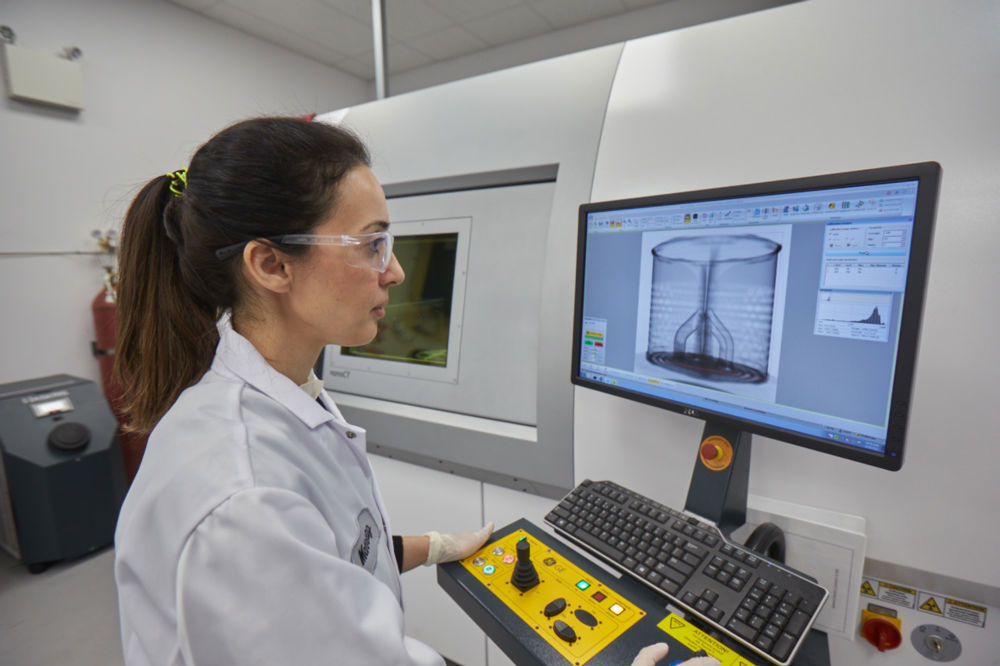
We know that your reputation, market competitiveness, and safety record hinge on your ability to continuously deliver high-quality products. Burloak’s robust quality assurance solutions are designed to ensure that your AM components deliver on this vision.
From production to documentation, process control to delivery, we ensure the final product supports your success in the markets you serve.
THE EXPERTISE AND EXPERIENCE YOU NEED TO DELIVER THE HIGHEST-QUALITY AM PARTS.
Burloak’s depth of experience and robust skill set combined with our ability to leverage leading-edge equipment and technology enables us to reduce customer risk by ensuring exceptional, high-quality parts.
Our world-class laboratory is managed by highly skilled engineers and equipped with the most advanced technologies in the AM industry – all focused on driving unparalleled product performance, quality and reliability, including for highly regulated markets.
Leveraging a range of well-honed and proven techniques, processes and machines, our team will:
OUR GLOBALLY RECOGNIZED CERTIFICATIONS INCLUDE:
OUR DIVERSE RANGE OF IN-HOUSE EQUIPMENT AND CAPABILITY SPAN:
CONNECT WITH OUR TEAM.
WE'RE HERE TO HELP.
Fill out the form below and we'll be in touch with you shortly.
